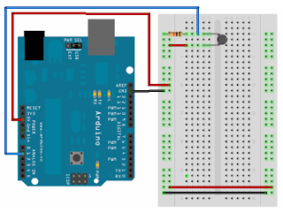
I made a new mistake in my attempt to make a hot plate PI controller: The thermistor I selected from eBay was an unbranded China thermistor marked with "10k ohm 103 NTC Thermistor"with no datasheet. I thought it would be easy to obtain the datas for the thermistor, but so far I have not been able to find any other info than what the seller is saying:
Model: CP_RM_103 NTC Thermistor
Resistance: 10KΩ
Resistance tolerance: +/- 10%
Temperature: 30°C to +125°C
I have sent an email to the seller as a last effort to get a datasheet for the thermistor, but I have doubts that I will get it.
I wanted to set up a test to check the accuracy of the thermistor in combination with the pre set parameters in the arduino library for thermistors. I soldered a wire to the thermistor, filled a pot with 1 liter of spring water, submerged the thermistor and boiled the water. When boiling temperature 100°C is reached the chart for temperature with stabilize at 100 degrees as water is vaporized.
First some theory:
Thermodynamics has equations describing how a volume will be heated. When there is no flow in or out of the volume the heating equation reduce to:
Cp*ρ*V*dT/dt=P+h(T0-T)
Where
Cp is specific heat capacity. For water Cp=4181.3 J/(kg*K)
ρ is the density. For water ρ=1000 kg/m^3
V is the volume. For my experiment I use 1 liter=1e-3 m^3
T is the temperature in the volume.
T0 is the temperature of the neighboring. The air temperature is about 22°C
P is the power of the heating source. I use two different boiling plates with 1.4 and 1.5 kW
h is the heat conduction number
If no energy is transferred to the environment with no other losses whatsoever I get:
Δt=Cp*ρ*V*ΔT/P
I am using two different hot plates:
1. A 1.5 kW standard hot plate. Ideal time for boiling 1l water should be 262 seconds, about 4 minutes.
2. A 1.4 kW induction hot plate. Ideal time for boiling 1l water should be 281 seconds, about 4,5 minutes.
The ideal heating time is based on the tap water being 6°C.
After modifying the LabVIEW VIs used with the thermistor and servo to also save raw voltage data to disk and importing to excel I get these curves:

A couple of things can be observed from the charts:
Model: CP_RM_103 NTC Thermistor
Resistance: 10KΩ
Resistance tolerance: +/- 10%
Temperature: 30°C to +125°C
I have sent an email to the seller as a last effort to get a datasheet for the thermistor, but I have doubts that I will get it.
I wanted to set up a test to check the accuracy of the thermistor in combination with the pre set parameters in the arduino library for thermistors. I soldered a wire to the thermistor, filled a pot with 1 liter of spring water, submerged the thermistor and boiled the water. When boiling temperature 100°C is reached the chart for temperature with stabilize at 100 degrees as water is vaporized.
First some theory:
Thermodynamics has equations describing how a volume will be heated. When there is no flow in or out of the volume the heating equation reduce to:
Cp*ρ*V*dT/dt=P+h(T0-T)
Where
Cp is specific heat capacity. For water Cp=4181.3 J/(kg*K)
ρ is the density. For water ρ=1000 kg/m^3
V is the volume. For my experiment I use 1 liter=1e-3 m^3
T is the temperature in the volume.
T0 is the temperature of the neighboring. The air temperature is about 22°C
P is the power of the heating source. I use two different boiling plates with 1.4 and 1.5 kW
h is the heat conduction number
If no energy is transferred to the environment with no other losses whatsoever I get:
Δt=Cp*ρ*V*ΔT/P
I am using two different hot plates:
1. A 1.5 kW standard hot plate. Ideal time for boiling 1l water should be 262 seconds, about 4 minutes.
2. A 1.4 kW induction hot plate. Ideal time for boiling 1l water should be 281 seconds, about 4,5 minutes.
The ideal heating time is based on the tap water being 6°C.
After modifying the LabVIEW VIs used with the thermistor and servo to also save raw voltage data to disk and importing to excel I get these curves:

A couple of things can be observed from the charts:
- The heating curve for the induction hot plate is very erratic. This is likely because induction is basically fast alternating current through a coil. This creates a magnetic field that again induces current in the sensor wire. If better results are to be obtained with an induction cooker I need a shielded thermistor.
- Both measured heating curves for the induction and standard hot plate has a measured boiling temperature of about 110°C. This is probably due to wrong values for this sensor set for the Steinhart-Hart equation.
- The zero crossing with the y-axis is above the temperature of the tap water temperature. This is again probably due to wrong values in the Steinhart-Hart equation.
- Some drops are observed for the standard hot plate. This is due to different temperatures when the thermistor touched the pot and when it was only in contact with water.
- The slope for the induction cooker is very close to the ideal curve, thus the induction cooker is very efficient at transfering energy into cooking water.
- The induction hot plate and pot can be modeled as an integrator without time delay. The standard hot plate can probably be modeled as an integrator with a time delay included. When heating a larger amount of water I am expecting more energy to be transfered to the environment, and the curves will probably take the shape of a "time-constant with time-delay" process.
Now I need to search a little more to try finding some information about the sensor specs. This in combination with the measured curves will probably give me everything I need to know to calibrate the thermistor.


